Tag Archive for: systems engineering

Digital Engineering

Digital engineering is an integrated approach that uses authoritative sources of system data and models as a continuum across disciplines to support lifecycle activities from concept through disposal. In the simplest of terms, it is the act of creating, capturing, and integrating data using models and innovative technology in an orchestrated manner in order to unlock greater value and provide positive impacts on cost and schedule. This integrated approach means that the data from the digital models such as CAD models, electrical circuit models, system models, and software models as well as the domain discipline processes are orchestrated tightly. Hardware, systems, and software engineers are now working much more closely to design and develop systems. 

Digital engineering is a movement that takes shape in many industry segments such as medical device development, automotive, defense, consumer electronics, and aerospace to reduce the pains of developing new products. The U.S. Department of Defense (DoD) has a poor track record of fielding new systems on time and within budget. Acquisition teams are mired in antiquated processes and are risk averse to attempt improvements if it causes too much organizational friction.  

The DoD has recognized its deficiency and has identified the following challenges with their current acquisition engineering process: 

  • It has a linear acquisition process that is not agile or resilient 
  • Stakeholders use stove-piped infrastructures, environments, and data sources to support various activities throughout the lifecycle 
  • Communication, collaboration, and decisions happen through static disconnected documents and subject to interpretation 
  • The existing practices are unable to deliver technology fast enough 

The Drive for Evolution in Engineering Practices 

Kristin BaldwinActing Deputy Assistant Secretary of Defense for Systems Engineering, wrote that, “In this era of rapid growth in technology, information, and complexity, we need to evolve our engineering practices. This evolution incorporates advancements in our engineering methodologies (methods, processes, and tools) to enable data-driven decision-making throughout the acquisition lifecycle.” 

In 2018 the US Secretary of Defense encouraged everyone to adopt new practices in order to modernize delivered systems and prioritize the speed of delivery. This encouragement was backed by a Digital Engineering Strategy which aims to allow the DoD and industry partners to work more collaboratively at the engineering level. 

DoD’s Expected Benefits of Digital Engineering 

Expected benefits of digital engineering include betterinformed decision making, enhanced communication, increased understanding of and confidence in the system design, and a more efficient engineering process 

The Top Five Goals of DoD’s Digital Engineering Strategy 

  1. Formalize the development, integration, and use of models to inform enterprise and program decision making
  2. Provide an enduring, authoritative source of truth
  3. Incorporate technological innovation to improve the engineering practice
  4. Establish a supporting infrastructure and environments to perform activities, collaborate, and communicate across stakeholders
  5. Transform the culture and workforce to adopt and support digital engineering across the lifecycle

There is a dire need to reduce the red tape without compromising the federal laws of oversight.  

Smart Systems Engineers 

A systems engineerprimary job is to work with the end users who are paying for the product. They have “operational requirements” that must be satisfied so that they can meet their mission needs.  

The current vision for the past decade has been to leverage Model Based Systems Engineering (MBSE) and use models to analyze and manage those requirements to ensure they are met at the end of the product development.  

The systems engineer becomes the translator from the electrical engineers to the mechanical engineers to the computer scientists to the operator of the system to the maintainer of the system to the buyer of the system. Each of these teams speaks a different language.  

The idea of using models was a means to provide communication in a simple, graphical form yet, only a tiny percentage of programs have demonstrated MBSE’s utility to achieve this vision. Smart systems engineers today recognize that models need to be expressed in more consumable formats to the broader stakeholder community so that communication and collaboration can take place. 

Jama Software’s Digital Engineering Bridge 

Jama Connect helps satisfy the DoD Digital Engineering Strategy’s first goal (formalize the development, integration, and use of models to inform enterprise and program decision making) by acting as a digital engineering bridge that connects the model world with the document world.  

Time consuming and error prone methods of data consumption via documents, spreadsheets, and legacy requirements tools introduces program risk and increases cycle time to the program timeline.  

Jama Connect’s unique user interface (UI) allows non-technical stakeholders to visualize a model of the system of interest and interact with the requirements in familiar views like documents and spreadsheets.  

The Benefits 

Whether Jama Connect is used in conjunction with MBSE SysML models or used as a standalone digital engineering platform, the system provides: 

  • Visualization of the shared system model and the status of its artifacts in the development lifecycle 
  • System and behavioral diagrams 
  • Faster requirements development 
  • Verification and validation of requirements developed in the model 
  • Mechanisms for broader audience communication and participation – tool specialists are not needed 
  • Baselining of requirements 
  • Requirements attribute management and workflow 
  • Requirements decomposition and tracing 
  • Specialized document generation and data reporting 

 Using Jama Connect in the application of MBSE to create models is supported by a series of pre-defined views and its underlying relationship ontology which enforces the rigor and consistency demanded by the framework. 

Jama Connect can be used in conjunction with dedicated SysML tools or as a standalone system. In fact, the data in Jama Connect is organized much in the same fashion as that in a modeling tool and performs many of the same functions. This is what makes it very attractive to organizations that do not have enough staff trained to use dedicated SysML graphical modeling tools. 

What Are Requirements in Jama Connect? 

From a big picture perspective, requirements themselves are the digital thread that connects the stakeholders stated needs and constraints to the system, hardware and software design that articulate to developers what must be developed. The notion that a “document” needs to exist for requirements to be captured and managed is a paradigm that the Digital Engineering Strategy is meant to eliminate. Jama Connect and modeling tools maintain requirements as atomic, individual objects that can then be consumed by all engineering disciplines in their own fashion. The overhead of maintaining documents just so they can be communicated to non-technical stakeholders is eliminated.  

There is also misconception that requirements engineering is performed only by systems engineers. A more agile approach to requirements engineering is when all stakeholders are validating requirements as they are being written (or as close to real time as possible). But this is difficult since a SysML model requires a specialist with many months of technical training to be able to read and understand. By using Jama Connect instead of documents or legacy requirements tools, the primary means for communication moves away from static and disconnected documents and shifts the paradigm to models and data serving as the basis for connecting traditionally siloed elements  providing an integrated information exchange throughout the lifecycle. 

Authoritative Source of Truth? 

The DoD has used the phrase single source of truth for decades, so much so that it has become the butt of ridicule. Misaligned tools and processes foster data to be stored in documents since that is the only medium that can be shared across vast varieties of stakeholders. This practice has led to: outright errors in data since it is difficult to keep track of the versions of documents; increases to the development timelines in order to just produce “documents” that are polished in formatting more suitable for print purposes; and increases to the overall cost since contractors have to charge for the additional document production time and publishing expertise. It is common for engineers to complain more of their time is spent producing pretty documents than doing engineering work. 

The Digital Engineering Strategy is attempting to combat the “where’s the latest document” question by describing in their second goal an authoritative source of truth. “The authoritative source of truth facilitates a sharing process across the boundaries of engineering disciplines, distributed teams, and other functional areas. It will provide the structure for organizing and integrating disparate models and data across the lifecycle. In addition, the authoritative source of truth will provide the technical elements for creating, updating, retrieving, and integrating models and data.”  

The Jama Connect platform is purpose-built to facilitate data sharing across various stakeholder disciplines and location boundaries. An easy to use web UI is used to capture and work with both data as well as the real-time decisions and feedback taking place around that data which keeps all stakeholders informed when change occurs and makes sure everyone gets the content they need—right when they need it. The result is that stakeholders can now access the most recent versions of data that engineers are working on without having to rely on document exports – the root of all waste. 

Fitting Within the Infrastructure 

No one tool alone will fulfill the new Digital Engineering Strategy and so to avoid the same problem of stovepipes that documents bring, the infrastructure and the tools used must become more consolidated and collaborative. Tools whether it is a MBSE tool, software engineering tool, testing tool, or CAD tool needs to have its data easily integrated with the rest of the tools within the infrastructure.  The “DoD’s strategy is to focus on standards, data, formats, and interfaces between tools rather than being constrained to particular tools.” This is probably the most difficult of all goals to achieve, not because of the lack of data exchange standards or capabilities provided by the vendors, but simply because of the distributed nature of the development teams themselves.  

In a contractor supply chain model, customers and their contractors perform their work on their own networks which are disconnected from each other. And even when working solely at a government site, classification levels force segregation of data onto different networks. Strategies to deal with integrating the data in the complex environment must be planned for.  

Jama Connect’s foundational architecture eases integration within the tool ecosystem. It has a built-in RESTful API and supports the industry standards OSLC and ReqIF formats for exchanging data. These important capabilities mean that when organizations go to integrate their digital engineering tools, numerous readily available 3rd party integration platforms are available; and in many cases already have templates to connect the endpoints in place.  

Parting Words 

There isn’t a single silver bullet to digital engineering, but I hope you leave this post with some ideas, some encouragement, and maybe some new determination to start your digital engineering journey. 


To learn more on the topic of requirements management, we’ve curated some of our best resources for you here.
 SEE MORE RESOURCES


2020s predictions: MBSE, model-based systems engineering, Intercax

As we enter a new decade of technological advancements, Jama Software asked select thought leaders from various industries for the trends and events they foresee unfolding over the next 10 years.

In the second installment of our 2020s Predictions series, we’re featuring predictions from Dirk Zwemer, President at Intercax, a global innovator in the field of model-based systems engineering (MBSE).

Jama Software: What are the biggest trends you’re seeing in MBSE right now and how are they impacting product development?

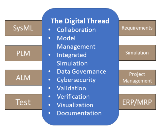
Dirk Zwemer: The biggest trend we’re seeing is the growing realization that MBSE is not a function of any one software tool, not PLM, not SysML, not requirements. The goal is the Digital Thread, the complete set of domain models organized, connected and version-managed in a way that allows everyone on the development team to find the data they need to do their jobs. Each discipline and each organization have a seat at the MBSE table (Figure 1).

MBSE Model-based system engineering and the digital thread
Figure 1 Seats at the MBSE Table


Implementation of the Digital Thread is still incremental in every enterprise. Early adopters look for specific integrations that enhance collaboration between team members, speeding completion of tasks and reducing errors from domain model inconsistencies. As they implement the Digital Thread more fully, they realize even greater gains in model validation and verification, which allows deeper exploration of the system design space within project schedules.

JS: What are some continuing or new trends in MBSE you expect to see over the next decade?

DZ: First, the engineering software tools and the Digital Thread infrastructure that connects them are all becoming scalable enterprise applications, sharing services and data either in the cloud or in on-premises servers. Standard interfaces such as RESTful or OSLC APIs will help support this, but the great heterogeneity of data, models and use cases will handicap approaches that restrict themselves to these technologies.

Second, no single MBSE methodology will be universally adopted, so flexibility in searching, visualizing, and documenting the Digital Thread will become important.  Tools with a “one size fits all” interface will be at a disadvantage relative to open source, open standard and third-party components that can give users the reports and metrics they need with minimal effort and cost.

Third, MBSE is moving downstream through the system lifecycle. The Digital Thread will cover: 

Conceptual Design Detailed Design Manufacturing & Logistics

With respect to tool integration, this will initially involve:

SysML PLM MRP

And we can expect to see increasing activity on this bridge. The advantages of devops processes in the software world will be increasingly obtainable for cyber-physical systems, as well.

JS: What sorts of process adjustments do you think development teams will need to make to accommodate these changes?

 DZ: Practicing good data governance will be the biggest adjustment for most development teams building the Digital Thread.

  • Cybersecurity will be an immediate concern. With the rollout of CMMC v0.6 (Cybersecurity Model Maturity Certification), DoD contractors, primes on down, will need audited cybersecurity practices to compete for government contracts starting in 2020. Information sharing will be particularly impacted.
  • While cybersecurity is nominally concerned with preventing access by bad actors, information access by collaborators is also an issue. Process teams will look for ways to selectively share data, e.g. between customer and supplier, that prevent the partner from accessing deeper levels of proprietary technology.
  • If the Digital Thread shares information between repositories, process teams will need to explicitly define data ownership, i.e. which repository is master, and processes for data comparison, notification, and update.
  • All these adjustments will be easier if the enterprise adopts standard, well-documented authentication mechanisms. In too many organizations, these have grown ad-hoc, different for each repository, and with no central management or knowledge base. Implementing the Digital Thread in such environments will prove frustrating, so common authentication protocols will be needed.

JS: What do you think will remain the same in MBSE throughout the 2020s?

DZ: While not absolutely necessary, architecture modeling will remain an important part of MBSE and SysML will remain the dominant architecture modeling language. The SysML v2 Submission Team is working under the auspices of the Object Management Group to keep SysML relevant, with a final submission target of June 2021. Proposed changes will make SysML more precise, intuitive, and reusable, especially in the area of modeling usages and variant designs. A new underlying metamodel and a companion standard for SysML API and Services will open new opportunities for model creation, management and visualization. Together, these new features should broaden the reach of SysML across the development team while reducing the barriers of learning new tools, terminology, and notation.

JS: Anything else you’d like to add?

 As new MBSE adopters flood the market and existing users refine their processes, the “Voice of the Customer” will be heard louder than ever. Buyers will want tools that are easy to use, cost-effective, and customer-configurable rather than vendor-customized. There will be plenty of opportunities for newer vendors that can meet these needs.

To learn more about the growing number of organizations adopting product development solutions to manage the complexity of connect systems, download our eBook, Your Guide to Selecting the Right Product Development Platform.

Team Collaboration Strategies for Systems Engineers

Complexity is nothing new. For decades, systems engineers have participated in new product development processes on internal teams, driving complicated projects to market under old rules, methods, and technologies.

But today’s highly-competitive markets offer new complexities that no longer work within the old rules of product development. According to McKinsey Global Institute, “the number of connected machine-to-machine devices has increased 300% since 2008.” Similarly, Machina Research — now part of Gartner — estimates that the number of connected machine-to-machine devices will increase from 5 billion in 2014 to 27 billion by 2024.

An Increasingly Complex Product Development Process

In an environment where modern systems are getting “smarter” and more complex every day, the product development process required to build them is also growing increasingly complicated.

Today’s systems engineers face new challenges such as:

  • Tight operational margins
  • Accelerating rate of innovation
  • Increasingly complicated end-user demands
  • Heightened focus on getting to market faster
  • Increased and changing regulations

Download this recent report by Engineering.com to learn more about the gap between the increasing complexity of products and requirements management.

Research conducted by Forrester Consulting on behalf of Jama Software identified five obstacles to optimized product development:

  • Unclear or changing requirements coupled with lack of timely feedback for solutions
  • Lack of focus caused by conflicting stakeholder priorities, assumptions, and unclear objectives
  • Difficulty collaborating across globally-distributed teams
  • Unnecessary handoffs and delayed decisions
  • Increased collaboration across diverse roles, including executives, operations, marketing, and quality assurance

In an environment that introduces so much complexity into the product development process, strategic team collaboration offers one of the best ways to address the challenges and obstacles of the modern product development landscape.

Strategic Team Collaboration: The Key Enabler of Innovation for Systems Engineers

Teams that still operate in silos with outmoded systems will not be equipped to meet the demands of the market going forward. In this era of rapidly accelerating change, strategic team collaboration is the key to improving the product development process for all team members. And in this era, the “team” includes everyone across the supply chain.

Today’s market demands require companies to build partnerships and seek solutions with more specialized materials. These partnerships mean greater sharing of data across distributed teams, partner organizations, and business units, sending a ripple effect through the supply chain as subsystem suppliers must anticipate features on the finished products and get ahead of release schedules and component costs.

But for systems engineers used to working on internal, siloed teams, these new partnerships present previously unforeseen challenges. What worked before doesn’t work today. Systems engineers need new strategies.

Developing complex products with partners requires a common vision. Learn how better requirements management helps facilitate the collaboration process by watching our webinar.

Strategies for Modern Requirements Management

In the new product development landscape, meetings, emails, and hallway chats are no longer sufficient for making decisions that impact the entire team. Modern systems engineering must include means for live data to be shared and accessed by teams anywhere in the world at any time.

Today’s product teams must be able to coordinate across departments, roles, companies, and geographic boundaries. The old way of sharing documents via email attachments and having meetings to discuss decisions doesn’t work when you need to work faster than ever before.

To meet the demands of the modern marketplace, systems engineers should implement practices such as the following:

  1. Establish a common definition of success. Teams need alignment on what they are building so they don’t waste time. Clarify expectations up front. What do the terms “define,” “build,” and “test” mean, for instance? What does success look like based on feedback loops such as customer interviews and design reviews? Define the “why” at the very beginning of the project.
  2. Empower better decision making. When the whole team is clear on the “why” defined at the beginning of a project, everyone is equipped to make better decisions. Good decisions need situational awareness, comprehension of impact, and a way to gather input from others. When responsibilities are clearly defined, those involved are empowered to initiate and resolve follow-up questions and issues.
  3. Tighten up your traceability. Certain industries need to demonstrate compliance with regulations. Traceability analysis proves your system holds up under regulatory demands and meets contractual terms. In order to tighten this process, coverage analysis can help a team find gaps and understand positive and negative progress. Extend traceability beyond engineering processes to link development and test activities back to the business rationale.
  4. Collaborate with purpose. Connect everyone on the team to relevant data that’s tied to the work. Don’t make decisions outside the process, such as in documents or emails.
  5. Reuse your IP. Repurpose entire IP blocks – design artifacts, specifications, test cases, content for data sheets, and process information.

Today’s product and system development environment may be complex, but systems engineers have an opportunity to optimize project management for success. To learn more, download our white paper, “Product Development Strategies for Systems Engineers.”


In 1967, computer scientist and programmer Melvin Conway coined the adage that carries his name: “Organizations that design systems are constrained to produce designs that are copies of the communication structures of these organizations.”

In other words, a system will tend to reflect the structure of the organization that designed it. Conway’s law is based on the logic that effective, functional software requires frequent communication between stakeholders. Further, Conway’s law assumes that the structure of a system will reflect the social boundaries and conditions of the organization that created it.

One example of Conway’s law in action, identified back in 1999 by UX expert Nigel Bevan, is corporate website design: Companies tend to create websites with structure and content that mirror the company’s internal concerns — rather than speaking to the needs of the user.

The widely accepted solution to Conway’s law is to create smaller teams focused around single projects so they can iterate rapidly, delivering creative solutions and responding adroitly to changing customer needs. Like anything else, though, this approach has its drawbacks, and being aware of those downsides in advance can help you mitigate their impact.

Here, we’ll unpack the benefits of leveraging smaller teams; assess whether Conway’s law holds up to scrutiny by researchers; and lay out how to balance the efficiency of small, independent teams against organizational cohesion and identity to build better products.

Smaller Teams Can Yield Better Results

Plenty of leading tech companies, including Amazon and Netflix, are structured as multiple (relatively) small teams, each responsible for a small part of the overall organizational ecosystem. These teams own the whole lifecycle of their product, system, or service, giving them much more autonomy than bigger teams with rigid codebases. Multiple smaller teams allow your organization to experiment with best practices and respond to change faster and more efficiently, while ossified, inflexible systems are slow to adapt to meet evolving business needs.

When your organization structure and your software aren’t in alignment, tensions and miscommunication are rife. If this is your situation, look for ways to break up monolithic systems by business function to allow for more fine-grained communication between stakeholders throughout the development lifecycle.

Testing Conway’s Law

In 1967, the Harvard Business Review rejected Conway’s original paper, saying he hadn’t proved his thesis. Nevertheless, software developers eventually came to accept Conway’s law because it was true to their experiences, and by 2008, a team of researchers at MIT and Harvard Business School had begun analyzing different codebases to see if they could prove the hypothesis.

For this study, researchers took multiple examples of software created to serve the same purpose (for example, word processing or financial management). Codebases created by open-source teams were compared with those crafted by more tightly coupled teams. The study found “strong evidence” to support Conway’s law, concluding that “distributed teams tend to develop more modular products.”

In other words, there’s definitely some justification for the idea that smaller teams will work more effectively and produce better results, while bigger groups may lack cohesion and exhibit dysfunction.

Organization First, Team Second

As a recent Forbes article noted, there are potential drawbacks to letting Conway’s law guide the structure of your organization. The thinking goes that “once you entrench small teams in this way, their respect and loyalty for that team often comes to outweigh their allegiance to the organization as a whole… Teams in disparate locations end up forming strong but exclusive identities as individual departments.”

So how do you balance the benefits of small, nimble groups against an organization-wide sense of solidarity, cooperation, and transparency?

Platforms that enable organization-wide collaboration can break down the barriers erected by Conway’s law without robbing small teams of their independence and agility. Josh McKenty, a vice president at Pivotal, argues that using collaborative platforms can neutralize the sense of otherness, of separateness, that can inhibit organization-wide cohesion: “Platforms can allow businesses to cultivate a sense of ‘we’re all in this together,’ in which everyone is respected, treated with mutual regard, and can clean up each other’s messes – regardless of whether they created the mess in the first place,” McKenty told a conference audience in 2017, according to Forbes.

That solidarity is crucial in complex product and systems development, where rapidly shifting requirements, evolving standards, and updated customer specs require consistent and dedicated communication within and across teams. If your teams are forming strong bonds, that’s terrific, but you don’t want those bonds to become exclusionary. If teams are turning into cliques, your organization has lost its internal cohesion.

A collaborative platform that unites disparate teams across functions and locations can help you actualize the benefits of small, focused teams without losing coherence.

To learn more about success strategies for systems engineers and developers, check out our whitepaper, “Product Development Strategies for Systems Engineers.”

Product development

Close gaps in product development with Jama Connect™ and LDRA

Interested in closing gaps in your product development lifecycle? It’s no secret that developers of mission-critical software are facing increasingly complex system requirements and stringent standards for safety and efficacy. That’s why Jama Software has partnered with LDRA to deliver a test validation and verification solution for safety- and security-critical embedded software. LDRA has been a market leader in verification and software quality tools for over 40 years. They serve customers across the aerospace and defense, industrial energy, automotive, rail, and medical device industries.

Integrating TÜV SÜD-certified Jama Connect with the LDRA tool suite gives teams bidirectional traceability across the development lifecycle. This transparency helps development teams build higher-quality products and get to market faster while mitigating risk. Whether teams are working from a standards-based V model or applying an Agile, Spiral, or Waterfall methodology, employing Jama Connect in concert with the TÜV SÜD- and TÜV SAAR-certified LDRA tool suite closes the verification gaps in the development lifecycle, helping to ensure the delivery of safe and secure software.

Let’s dive into some details to understand the value of using Jama Connect and the LDRA tool suite.

Requirements and test cases form the bond between Jama Connect™ and LDRA

Product managers and engineers use Jama Connect to manage requirements and testing from idea through development, integration, and launch. Managing requirements in the Jama Connect platform allows users to align teams, track decisions, and move forward with confidence that they are building the product or system they set out to build.

LDRA imports Jama requirements and test cases, mirroring the structure and levels of traceability established from the decomposition of stakeholder requirements down to software requirements and test cases. With the Jama artifacts in the LDRA tool suite, traceability down to the code can be realized and verification and validation of requirements can begin.

During the Jama test case import, the user can choose the type of test case it corresponds to (e.g. unit test, system test, code review test) and let LDRA create a test artifact that will invoke the proper part of the LDRA tool suite and realize that test case type.

Part of realizing Jama test cases in the LDRA tool suite includes the ability to follow the steps defined in the Jama test case description (e.g. inputs, outputs, expected results). Test cases executed by the LDRA tool suite can be executed either on a host machine, in a virtual environment, or on the actual target hardware. Verification results are captured, and Pass/Fail status results are produced. The verification results can then be exported from the LDRA tool suite into the Jama test case verification status field.

By way of the Jama Test Run feature, the change in verification status and included user notes can be logged and committed. Additionally, if the user desires, the LDRA tool suite verification results can also be exported into the Jama requirement verification status field, giving the Jama user additional touch points to analyze.

Another benefit of the integration is Jama’s ability to create, link, assign, track, and manage defects discovered during testing with the LDRA tool suite.

Partnering with standards and safety experts on product development

Many industries and their applications have safety-critical requirements drawn from process standards like ISO 14971 and ISO 26262. These requirements demand a higher level of visibility and traceability that can be achieved with the Jama-LDRA integration.

LDRA is heavily involved in the international standards body. They help lead the DO-178 standard in the aerospace market for safety in avionics. LDRA is also a significant contributor to the MISRA software coding standard and other standards like CERT. Their tool suite is ISO 9001:2008-certified as a quality management system and TÜV SÜD- and TÜV SAAR-certified.

The Jama-LDRA partnership benefits not only LDRA customers in the military and aerospace needing to comply with standards like DO-178B/C, but also one of the fastest-growing industries, and the one that keeps LDRA the busiest: the automotive industry and their need to comply with ISO 26262. The Jama-LDRA partnership also addresses applications for safety and security in the medical device industry (IEC 62304), rail (EN 50128), and industrial controls and energy (IEC 61508).


RELATED: Increasing Efficiency in Testing and Confidence in Safety Standard Compliance

Certification and code analysis

LDRA helps users achieve certification in standards like DO-178B/C, DO-331, ISO 26262, Future Airborne Capability Environment (FACE), IEC 61508, and others. The LDRA tool suite lays out a set of objectives for the relevant process standard, along with corresponding artifact placeholders and sample template documents. This guiding project structure with built-in progress metrics gives the user an intuitive understanding of what is required to achieve certification and the day-to-day gains toward that goal.

A major key benefit to customers is LDRA’s ability to perform on target hardware testing or Run-For-Score (RFS). These customers have a very strict process for achieving certification wherein step-by-step testing is followed and results are logged and eye-witnessed.

LDRA also has its own proprietary code analysis engine. Starting with static code analysis, a debugging method that examines the source code before the program is run, LDRA generally finds potential coding flaws and security vulnerabilities prior to code compilation. Once the code has been compiled, testing can be further complemented by LDRA’s dynamic testing, structural coverage, and unit testing.

Build with certainty

The complementary capabilities and automation offered by Jama and LDRA deliver a powerful solution for the development and test verification of software systems in the product development lifecycle. Whatever software development approach your team chooses to employ, requirements- combined with Jama’s product lifecycle management capacities can help you deliver safe, compliant products on time and on budget.

To learn more about test management with Jama, take a deeper look at our solution and download the datasheet.


To learn more on the topic of test management, we’ve compiled a handy list of valuable resources for you!

A recent study of almost 300 design and engineering professionals conducted by Engineering.com and sponsored by Jama Software showed that not only are products increasing in complexity, but that many organizations are not equipped with the right tools to manage the intricacies of complex product development.

The study showed that over the last five years, unsurprisingly, most development teams have seen their products become more complex. In fact, 92% of respondents in the study reported experiencing at least one form of increasing complexity.

In fact, over the last five years, 76% of respondents reported dealing with three or more increased measures of complexity and 25% saw their products become more complex in five or more ways.

Here are the top three ways that products have become more complicated in the last five years, according to the study:

Mechanical Designs are Getting More Intricate

Part of what makes modern product development so complex is the volume of parts and components involved. The survey found that mechanical designs had become more intricate in the last five years for more than half (57%) of respondents. Not only are the number of components increasing, parts are sourced from multiple vendors and are now much smaller and more technologically advanced, adding another layer of complexity to product development.

And with mechanical design intricacy comes increasingly complex requirements. The study showed that product feature requirements are critical to 79% of respondents and that in order to properly manage intricate mechanical designs, organizations need an information system to handle requirements throughout each stage of product development. Further, teams using a formal, purpose-built requirements management platform were less likely to experience product outcome failures.

Download the Full Report Now

Electronic Components are Increasing

According to the study, about half of respondents (47%) said that products were becoming more complex because of the increasing number of electronic components. As the market continues to demand more connected products — think thermostats, lights and doorbells that all connect to your smartphone — product developers must incorporate more electronic components and software into their designs.

And while this won’t come as a shock to anyone, it’s clear that integrating more electronic components, embedded software and microprocessors necessitates clear and granular requirements management and testing. 

Teams Are Needing to Adopt Different Materials

Nearly half (43%) of respondents said that products are increasing in complexity because they are adopting new materials. And while this is true across all industries represented in the study, it’s especially true for the automotive industry.

Connected automobiles are rising in popularity and giving drivers new ways of interacting with vehicles while providing data directly to smartphones. Under the hood, many electric and connected vehicles work with entirely different designs and materials than traditional combustion engines, leading to faster performance and less maintenance.

And, of course, the race towards self-driving automobiles is bringing with it a whole new level of intense complexity that’s forcing teams to adopt new and innovative technologies and materials.

Managing Requirements in Complex Product Development

Perhaps the most interesting finding to come out of this report is that while 92% of respondents reported experiencing at least one form of increasing complexity, only 15% relied on a dedicated requirements management platform to help them manage that complexity. Further, without a purpose-built solution, the report showed that teams with ineffective requirements management were more likely to experience product outcome failures (83%) and reprimands by regulatory agencies (62%).

The report went on to conclude that the data showed that most design and engineering teams are producing increasingly complex products. Yet most teams haven’t been investing in the technology available that would help them manage the requirements this complexity demands.

To dive deeper into the relationship between rising product complexity and effective requirements management, download the full report: Design Teams: Requirements Management & Product Complexity.”

This article is Part 2 of a two-part series by our friends at BigLever Software.

Part 1 provided an introduction to Feature-based Product Line Engineering (PLE) and the “PLE factory” – which is a foundational concept in the new PLE ISO standards under development, as well as the underpinning of BigLever’s PLE approach.

As a reminder, PLE is an innovative engineering practice that provides a way to take full and ongoing advantage of the commonality shared across a product family, while efficiently and systematically managing the variation or differences.

In this article, we will take a closer look at the underlying concepts central to Feature-based PLE — the automated production line approach enabled by PLE — and the supporting technology foundation.

The PLE Automated Production Line

As discussed in Part 1, the underpinning of PLE is the PLE factory, which is much like a typical manufacturing factory except that it operates on digital assets rather than physical parts.

PLE allows an organization to create a “superset” supply chain of digital assets that can be shared across the entire product line. These digital assets are equipped with all the feature options offered in the product line.

Figure 1 provides an extended view of the PLE factory and how it enables the establishment of an automated production line that assembles and configures the shared digital assets based on the features that are selected for each product variation – enabling a fully unified, automated approach.

Figure 1: The PLE automated production line

Feature-based PLE enforces consistent treatment of all shared assets under the automated production line infrastructure, so that a full set of demonstrably consistent supporting artifacts can be systematically generated for each product.

Assets are designed in Gears, BigLever’s industry-standard PLE solution, with built-in variation points. Each variation point describes a piece of content in the shared asset whose participation in any product depends on a certain feature, or combination of features, being chosen.

When a product is built, the configurator uses the product’s feature-based description to “exercise” these variation points (that is, configure the asset to meet the needs of the product.)

Variation point mechanisms comprise: including or omitting the artifact; choosing one variant of the artifact (from an available set) to use in the product; or making fine-grained choices within an artifact such as including or omitting a requirement, section in a document or model element or block of code.

Under this shared-asset-with-variation-points paradigm, the artifacts that engineers create and maintain for the product line are supersets: Each has the content necessary to support any product in the product line. The configurator’s job may be seen as exercising the variation points to filter away content until only that needed for the product being built is left.

Variation points are expressed in terms of features, not products. The configurator does its work by comparing feature-based expressions that define a variation point to the feature choices that define a product.

Hence, the assets are configured to support feature selections; the supersets become product-agnostic. Among other benefits, this makes adding a new product to the portfolio exceptionally easy.

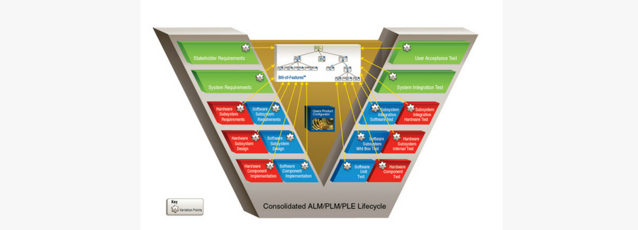
Figure 2 provides a closer look at the classic engineering V-model, recast for product line engineering.

Figure 2: Engineering V-model and PLE

Each phase across the lifecycle is augmented by the addition of variation points (indicated by the gear symbol) to the artifacts native to that phase.

A Bill-of-Features for a product, as shown at the top of Figure 1, corresponds to the feature selections within the feature profiles for that product. The yellow arrows illustrate that all of the variation points in all of the artifacts across the full lifecycle are synchronously and consistently configured according to the single consolidated collection of feature selections in the Bill-of-Features.

Gears and the PLE Ecosystem

As the technology foundation for the PLE factory, Gears is the all-in-one tool used to establish, organize, and operate an automated production line. More specifically, Gears provides the means to:

  • Create and maintain the production line
  • Build and maintain the feature catalog and Bills-of-Features for the production line
  • Attach shared assets to the production line
  • Edit shared assets to define variation points and create instructions to Gears for how to exercise them
  • Configure the shared assets to produce product-specific instances based on a Bill-of-Features

In a PLE context, requirements engineers work on requirements, software engineers work on software, test engineers build test cases, assembly engineers build bills of materials and parts lists, tech writers create user manuals, build engineers craft build scripts, and so forth. While these activities now happen in the context of the entire product line rather than individual products, the individual engineer’s job, by and large, remains the same.

However, under the PLE factory approach, we need the requirements engineers, software engineers, test engineers, and the rest to put variation points into their artifacts – and we want that process to be assisted and facilitated by automation that will eventually exercise those variation points. This means we need a way to support the specification and selection of variation in assets and artifacts from across the entire lifecycle. This is enabled via the PLE Ecosystem of tools and Gears Bridge integrations with those tools.

The PLE Ecosystem was established to allow engineers to continue to work in the technology and tool environments to which they are accustomed, while making those environments “product line aware”.

Tools in the PLE Ecosystem may be commercially available, open source, customized, integrated or proprietary. This PLE Ecosystem is important for ensuring that these tools work effectively with Gears for a consistent, compatible, fully unified PLE solution across all enterprise lifecycle phases.

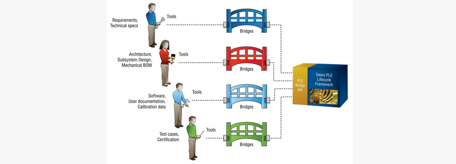
Gears interfaces with the tools in the PLE Ecosystem via integration bridges. Built on the PLE Bridge API, Gears Bridge solutions make tools product line aware by incorporating standardized variation point mechanisms and enabling the execution of PLE operations – such as product configuration, variation point editing and variation impact analysis – from within the tools.

Figure 3 illustrates Gears Bridge integrations using examples of shared asset types and tools.

Figure 3: Bridge integrations via the PLE Bridge API

The PLE Ecosystem includes tools from third-party tool providers such as IBM Rational, Aras, PTC, No Magic, Sparx, Microsoft, Perforce, MadCap, Open Source and more.

The PLE Bridge API also enables organizations to create bridges for connecting with additional engineering tools that are used in their tooling environment. The PLE Ecosystem continues to grow as BigLever, our partners, and our customers add new integrations and strengthen the capabilities of existing ones.

Engineering Gains Translate to Business Value

In this article series, we have explored how Feature-based PLE is not a “boutique” hand-crafted approach, but is proven, robust, and industrial-strength — centered around the factory paradigm and backed up by industrial-scale commercially available tooling.

We see this leading-edge approach being used by forward-thinking organizations to achieve dramatic reductions in the overall engineering effort required to design, produce, deliver and evolve their product lines. This, in turn, translates to major cost savings.

For example, Lockheed Martin reports an average of $47 million in annual cost avoidance using Feature-based PLE to produce the AEGIS Weapon System product line for the U.S. Navy.1 And another global aerospace defense company accumulated more than $746 million in cost avoidance based on its PLE approach for the production of the U.S. Army’s Live Training Transformation product line.2

These engineering efficiency gains and cost savings translate to major strategic business value for organizations employing Feature-based PLE — including order-of-magnitude improvements in time-to-market and product quality, increased product line scalability, and ultimately, a greater competitive advantage.

Note: Is your company interested in a BigLever and Jama Software integration? Let us know! We’re exploring the creation of a new Gears Bridge solution for Jama and looking for early adopters. Contact BigLever at info@biglever.com.

[1]  Product Line Engineering on the Right Side of the “V” by Susan P. Gregg, Denise M. Albert, and Paul Clements, Proceedings of the 21st International Systems and Software Product Line Conference (SPLC 2017), Sevilla, Spain. September 2017.

[2]  “Training and Simulation,” https://gdmissionsystems.com/c4isr/training-simulation/.

This is the first of a two-part series of guests post about Product Line Engineering (PLE) from our friends at BigLever Software

PLE is the engineering of a product line portfolio using a shared set of engineering assets, a managed set of features and an automated means of production. By “engineer,” we mean all of the activities involved in planning, producing, delivering, sustaining and retiring products.

PLE provides a way to take full and ongoing advantage of the commonality shared across a product family, while efficiently and systematically managing the variation or differences.

Managing a portfolio as a single entity with variation, as opposed to a multitude of separate products, brings enormous efficiencies in the development, production, maintenance and evolution of a product line portfolio.

The engineering improvements enabled by PLE are resulting in dramatic reductions in engineering cost and time-to-market, and order-of-magnitude improvements in productivity, product line scalability and product quality.

As PLE has evolved into an industrial-strength engineering discipline, modern state-of-the-art approaches — known as “Feature-based” PLE — have emerged to enable the industry’s most notable success stories. Feature-based PLE has been acknowledged as one of the foremost areas of innovation within the systems engineering field by INCOSE (International Council on Systems Engineering).

INCOSE is leading the development of new ISO standards for Feature-based PLE, in an effort to clearly delineate a disciplined, structured set of standards that can be applied to help engineering organizations adopt and successfully implement these proven approaches. BigLever Software is working in conjunction with INCOSE to support and facilitate this standards development.

This two-part article series explores the underlying concepts central to Feature-based PLE and illustrates how it provides a unified, automated approach.

In this article, Part 1, we provide a view into the “Feature-based PLE factory,” which is a foundational concept in the new ISO standards under development, as well as the underpinning of BigLever’s PLE approach.

And, we will also address why this innovative engineering paradigm is being adopted by a growing number of forward-thinking organizations across a spectrum of industries such as automotive, defense, aerospace, aviation, industrial systems and beyond.

The Product Line Engineering Factory

The underpinning of Feature-based PLE is the creation of a “PLE factory.” Briefly, a PLE factory comprises:

  • Collection of soft assets (that is, assets that can be represented digitally) shared across all the products in a product line
  • Set of specifications that define the products, in terms of the features that each contains
  • Product configurator that applies a specification to the digital assets in order to produce each product in the portfolio.

Manufacturers have long used analogous engineering techniques to create a line of similar products using a common factory that assembles and configures parts designed to be reused across the varying products in the product line.

For example, automotive manufacturers can create thousands of unique variations of one car model using a single pool of parts carefully designed to be configurable, with factories specifically designed to configure and assemble those parts. Modern PLE approaches, as specified in the new ISO standards, are known as Feature-based PLE because the factory is established and operated based on a single set of defined product features, which are offered by the entire product line.

BigLever’s Gears PLE Lifecycle Framework provides the technology foundation for the Feature-based PLE factory. Organizations use the Gears configurator as the factory’s automation component; the parts are the shared assets in the factory’s supply chain. A statement of the properties desired in the end product tells the configurator how to configure the assets. Figure 1 illustrates.

Figure 1: Feature-based PLE seen as a factory

The factory’s supply chain is shown on the left, in the form of shared assets that are configurable because they include variation points that are expressed in terms of the features available in each of the products. A product specification at the top (provided by Product Line Management) tells the configurator how to configure the assets coming in from the left, based on the features selected for a specific product. The resulting product, assembled from the configured assets, emerges on the right. This enables the rapid production of any variant of the assets for any of the products in the portfolio. Once this production line capability is established, products are instantiated — derived from the shared assets as determined by feature selections — rather than manually created.

In this context, products can comprise any combination of software, systems in which software runs or non-software systems that have software-representable artifacts associated with them. Some of these artifacts support the engineering process, while others are delivered alongside the product itself.

Shared assets are the building blocks of the products in the product line and are specifically engineered to be shared across the product line. They are the digital artifacts associated with the engineering lifecycle of the product.

Shared assets can include, but are not limited to:

  • Requirements
  • Design specifications
  • Design models
  • Source code
  • Build files
  • Bills of materials
  • Test plans and test cases
  • User documentation
  • Manuals and installation guides
  • Project budgets
  • Schedules
  • Work plans
  • Product calibration and configuration files
  • Data models
  • Parts lists and more

A feature is a distinguishing characteristic of a product. Features are analogous to the choices made, for example, when buying a new car. They typically express the customer-visible diversity among the products in a product line. The concept of a feature allows a consistent abstraction to be employed when making choices from a whole product configuration all the way down to the deployment of software components within a low-level subsystem in the architecture.

In practice, stakeholders throughout the entire portfolio’s environment are fluent in the language of features: marketers sell features that customers buy; testers test features; parts are added to support features; software programmers write code to implement features; requirements engineers specify features; and so forth. All of these roles are able to communicate meaningfully in this lingua franca, as opposed to the arcane languages of each one’s discipline.

This transition to a Feature-based PLE factory approach allows organizations to break down operational silos across the enterprise and achieve new levels of efficiency, interoperability and alignment among all aspects of planning, designing, delivering, maintaining and evolving a product line portfolio. 

Why Feature-based PLE – Now?

Manufacturers are being pushed to the edge of their capability by the exponentially growing complexity of today’s products and how they are engineered. Engineering teams are increasingly consumed by the mundane tasks of managing this complexity. Organizations face myriad challenges in finding new ways to tame this mounting complexity, and manage increasing product diversity, in order to bring products to market rapidly and efficiently, while still achieving the highest levels of safety and reliability.

This creates an extraordinary need and opportunity for dramatic improvements in the way complex product lines are engineered, delivered and evolved. Traditional product-centric approaches — where individual products within a product line are designed, produced and maintained separately — are simply no longer viable. Feature-based PLE has emerged as a proven, robust and industrial-strength solution for addressing this problem.

Stay tuned for Part 2 of this series, where we will explore in greater detail how the PLE factory works and the supporting PLE ecosystem of tool providers. We’ll also take a closer look at how the engineering efficiency gains and cost savings delivered by PLE translate to strategic business value including order-of-magnitude improvements in time-to-market, product line scalability, product quality and, ultimately, greater competitive advantage. 

In the meantime, gain some sharp insights into managing the growing complexity of systems, organizations, processes and supply chains with our resource, “Systems Engineering and Development.

Systems are getting more complex, from autonomous vehicles to smart energy grids to the Internet of Things, and systems engineering must keep pace.

Creating and testing physical prototypes is too expensive and time-consuming in many cases. Systems must rely on digital models until the final stages of development. But this raises a new challenge: with so many digital models in use, how do the systems developers keep them consistent and use them together effectively?

The requirements for a new class of digital frameworks for Model-Based System Engineering (MBSE) are becoming clear, and here are seven examples.

  1. MBSE supports a single, digital model of the system, the Total System Model (TSM)

MBSE replaces document-based systems engineering, where communications between engineers and models in different disciplines are by emails, slides or spreadsheets.

  1. Federation, not centralization, is the most practical strategy for building the TSM

Few organizations want to replace all their existing software tools for requirements, architecture, design, analysis and project management, or try to centralize all system data into a single database.

Federation calls for most of the system data and engineering efforts to remain invested in existing tools, but an MBSE Platform connects them. No single tool is indispensable or the hub for all connections.

  1. The MBSE platform will be an enterprise application

Systems engineering isn’t just for systems engineers anymore. The functionality to create, use, query and visualize the connections between model elements in different tools should reside in the cloud or an on-premises server.

It should also be available to all the members of the project team, through a variety of portals: computers, tablets and even smart phones. It must also be scalable, with rapid response times, to the largest projects with millions of elements.

  1. The MBSE platform supports the full system lifecycle

The platform must support the entire system lifecycle, creating a digital thread from design to manufacturing to operations.

Connecting design data to manufacturing, quality, logistics and field deployment data provides traceability and better diagnostics. It also requires that the TSM be configuration-managed, just as many of the individual domain models are.

  1. The MBSE platform must be methodology-independent

The platform should not enforce a specific workflow, so it should support multiple use cases.

These include connections that link disparate elements in different tools, and model transformations that share information across domain boundaries. It also implies the ability to program the platform through user-written apps and scripts to support any particular organization’s engineering processes.

  1. The MBSE platform should make the system engineer’s job easier

This includes the ability to make connections automatically under rule-based guidance.

It should also provide the ability to identify and evaluate the impact of extended chains of connection — the “line of dominos” effects that systems engineers are particularly responsible for. This requires powerful visualization and pattern-matching algorithms to pull the key factors out of the mass of data.

  1. The MBSE platform should protect proprietary information

Sharing data across organizational boundaries is rarely just a technical problem. The platform should respect the access constraints of the individual repositories and control sharing through mechanisms like common models that show only the data that each side has decided to share, but are linked to, and updated by, the hidden models on both sides.

The adoptions of MBSE integration approaches like those described above have implications for individual engineering tools themselves. In this environment, success engineering software tools will be:

  • Enterprise applications with robust, standards-based APIs
  • Specialized, doing a few things with excellence rather than trying to do everything

Dirk Zwemer is President of Intercax, which is pursuing the vision discussed in this article with Syndeia — from the Greek roots for “the practice of bringing things together.” It connects model elements in a range of engineering software tools, including Jama Connect™, in a vendor-neutral framework and applies modern graph theory and technology to the challenge of visualizing and querying large systems models. Just released, Syndeia 3.2 takes important steps toward a robust server-based enterprise application and greatly expands the range of users and use cases supported. To learn more, visit www.intercax.com/syndeia for more detailed information and video demonstrations.

do-254-feat

“The biggest risk is not taking any risk…In a world that is changing really quickly, the only strategy that is guaranteed to fail is not taking risks.”

– Mark Zuckerberg, CEO & Founder of Facebook

Although this is true of many of today’s greatest product innovations and the people behind them, when it comes to aerospace and avionics systems and product development, winning is rarely about taking a huge risk and having it pay-off. In fact, most of the time winning is about building a safe, reliable, working product. (Extra credit is given for products that come in on time, under budget, and exceed your customers’ expectations for usability and durability). Of course, to Mr. Zuckerberg’s well-established point, innovation typically demands some level of risk. The secret lies in taking on only an acceptable amount of risk relative to your design assurance levels.

At Jama Software, we know for certain that the more efficient the requirements management process and the more you can define and approve (reach consensus) requirements upfront, the higher your likelihood of coming in ahead of schedule and under budget – and mitigating those risks. In his new “DO-254 Costs Versus Benefits” whitepaper, Vance Hilderman points out the more assumptions that are minimized, the greater the consistency of requirements and their testability is assured, and iterations and rework due to faulty and missing requirements is greatly reduced. One of the leading causes of project failure is poor requirements management. The benefit of DO-254 is the rigor it adds to your requirements management process, thereby increasing your odds of success.

DO-254 can also help save you time by reducing the number of bugs found during testing. Vance states: “Since DO-254 mandates thorough and testable requirements along with design / implementation reviews, far fewer bugs will occur and the test / fix cycle should be expedited.” Voila! Not only will you have a better functioning product, but you will save time and money as a result of the process.

In our ongoing work with heavily regulated industries like Medical Device / Life Sciences, Aerospace, and Automotive, we often hear companies immediately associating cost with regulation. And although that is true, the benefits far outweigh the cost. One is that the most significant cost escalation across DO-254 DALs occurs between Level C and Level B – the cost for Level B is the same as for Level A. It is important to realize that the most expensive design iteration will be when you initially begin designing towards a standard. As you become more familiar with the regulations and rules, it will become easier, and you will also begin to be able to reuse requirements that are reviewed and approved to fit the standard. In complex, regulated environments an investment in DO-254 is not only strategic, but can maximize time to value and save from costly rework and technical debt.

To read Vance’s whitepaper where he goes in-depth on these ideas and concepts, please download the paper here.

And to learn more about how Jama can help you adhere to and provide traceable proof of adherence to these standards, please start a free 30 day trial today!